


Own the unlimited power of cloud-based collaborative measuring anywhere, anytime in Measure Map Online.
Have your own storage bucket, organize your projects in folders in your account that can be accessed from any device at anytime.
Get Started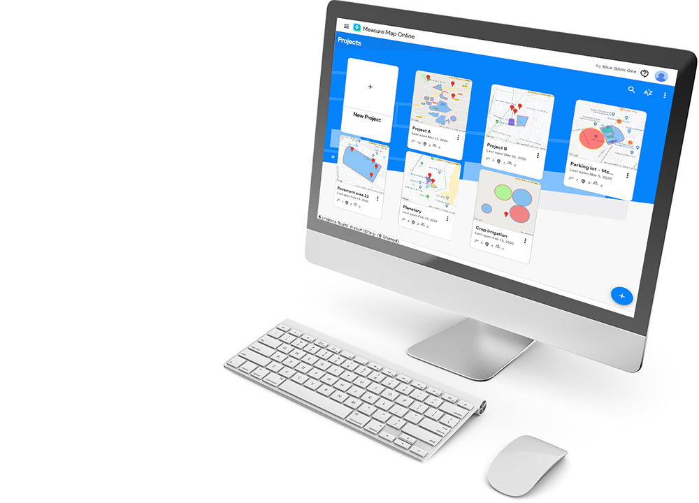
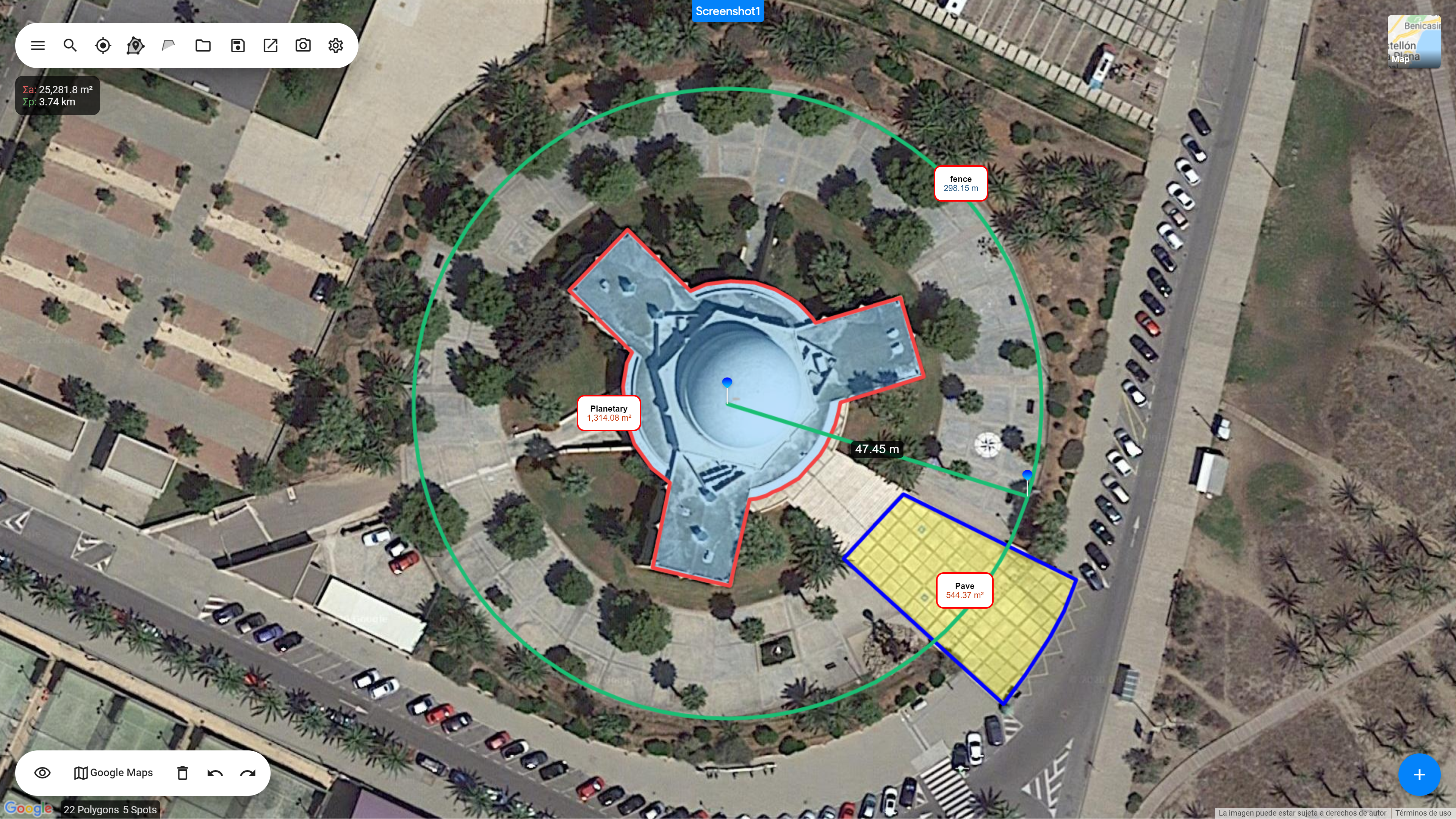
Once you're in a project, hold down your key or right-click your mouse to toggle the Crosshair and start measuring.
Learn More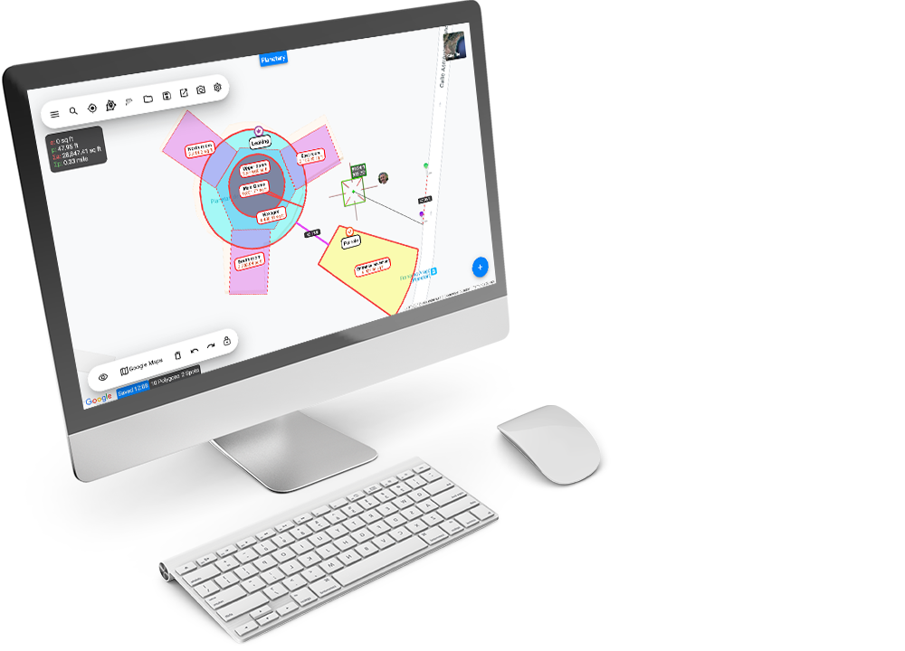
Have multiple measurements on the map by simply locking a polygon to create a new one. Keep repeating the process and you'll have all of your areas and distances measured on one single map.
Learn More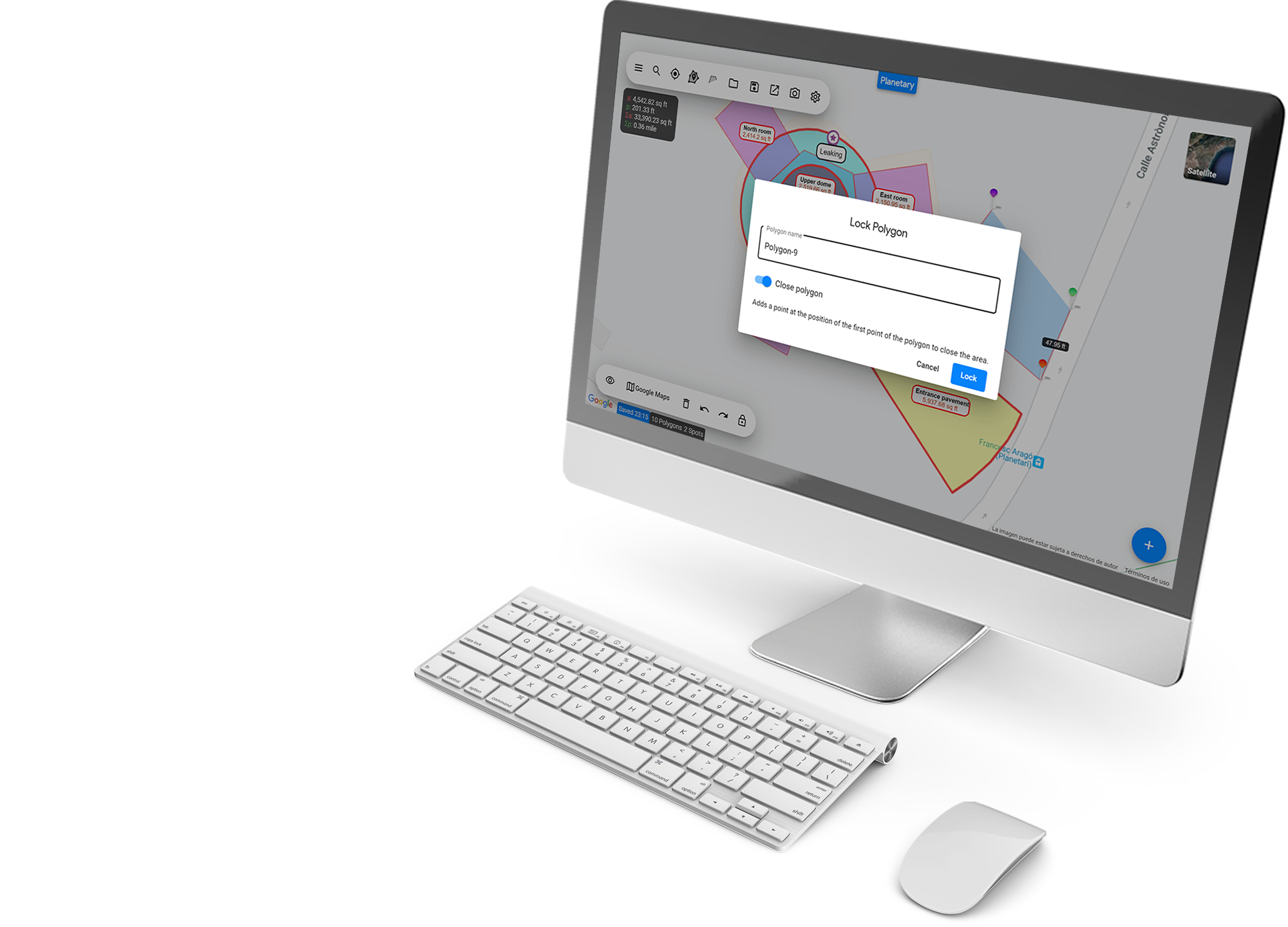
Share projects with your colleagues and clients instantly with a link and choose who can edit and who can view with our advanced sharing permissions settings.
Learn More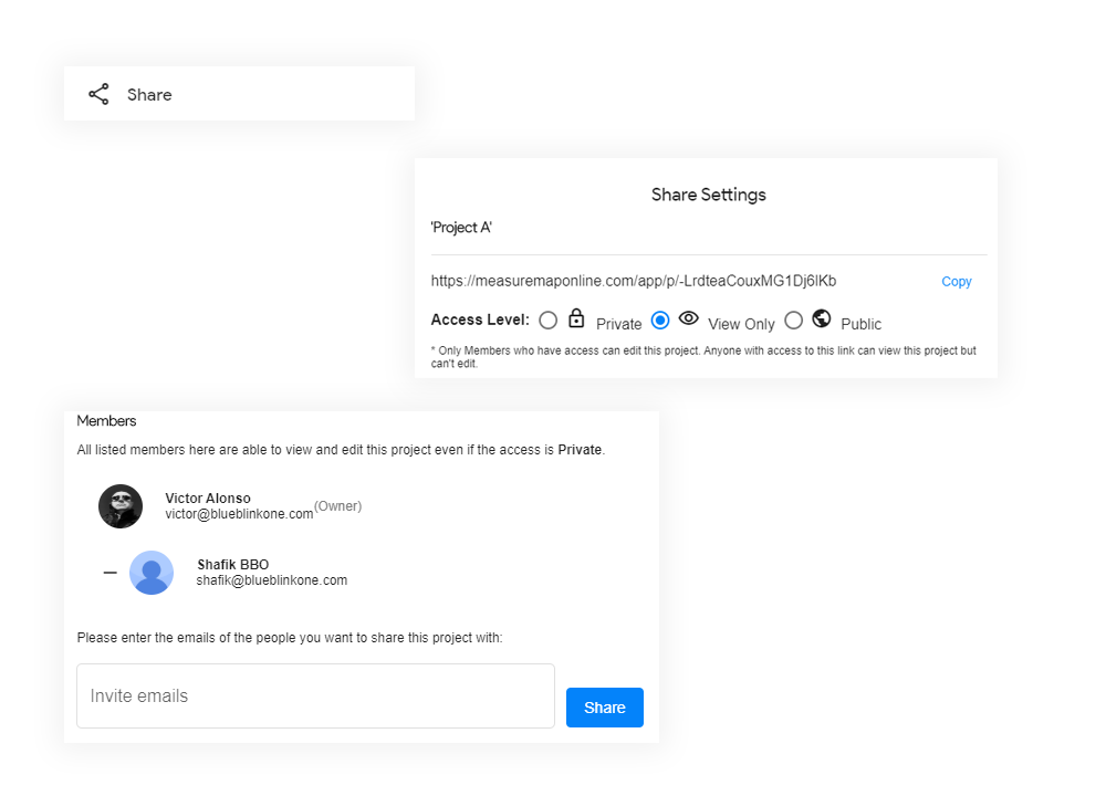
All changes are automatically saved to the cloud so you can access them from any other device. Work on shared projects with your colleagues in real-time, Google Docs style.
Learn MoreStay ahead of the game, make faster measurements and proposals
Get everything Measure Map has to offer. No additional charge. Choose the most suitable plan for you.
* Get a 30-day FREE Trial, no payment method required. solid edge material table
* Terms are subject to change. In the world of computer-aided design (CAD), geometry
In the world of computer-aided design (CAD), geometry is only half the story. While a 3D model defines the shape, size, and assembly relationships of a part, it is the material properties that define its physical reality. How much does it weigh? Will it withstand the applied load? How does it interact with other components in an assembly?
This guide will take you from a basic understanding of the Solid Edge material table to advanced customization, ensuring your data is accurate, consistent, and optimized for your specific engineering workflow. At its core, the Solid Edge Material Table is a database library. It stores a collection of material definitions that can be applied to parts and sheet metal documents. When you apply a material to a part, you are essentially linking that geometry to a specific set of physical properties defined in a material file (typically with an .mtl extension).
For users of Siemens Solid Edge, the central hub for managing these critical definitions is the .
Despite being one of the most frequently accessed dialogs in the software, the Material Table is often underutilized or misunderstood. Many engineers simply select "Steel" or "Aluminum" from the default list without understanding the impact on downstream processes like simulation, drafting, and 3D printing.